How To Interpret A Blueprint
All Categories
About Our Plans Building a Home Building Your Home Green Building Help and Support Hobbies & Recreation Home Building Tips and Information Home Design Home Exterior & Framing Homepage Articles House Plan of the Week How We Work Ideas and Inspiration Industry News Infographics Information & Resources Inspired Spaces Interior Design Kitchens Mascord News Modified Home Designs Outdoor Living Personal Stories Plan Support Products and Services Real Estate Remodeling & Renovating Showstoppers
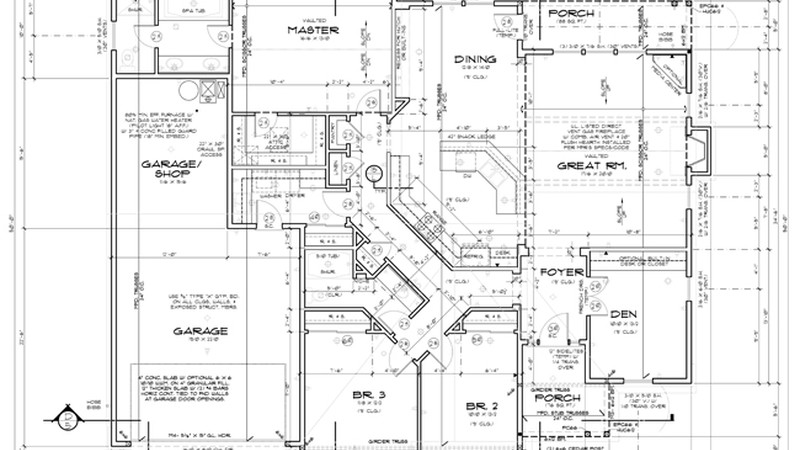
No doubt, some of the most interesting pages for you in your blueprints will be the floor plans. But to understand them, you will need to decipher the numbers and symbols that provide the keys to what they say. First, floor plans — and all of the other drawings in a set of blueprints. Prints are drawn to scale, usually one-quarter (¼) of an inch, meaning every one-quarter of an inch on the prints equals one foot of actual size. The simplest method for translating scale measurements into their actual size is to measure them with a scale ruler, which will indicate the conversion directly on the ruler. (Scale rulers are available at any crafts store and at many drugstores). Each page of the drawings should be labeled to indicate what size scale the home designer used when drafting the plans.
Some measurements, such as room dimensions, will be labeled directly on the blueprints with their actual size. These measurements are indicated with dimension lines, which consist of a solid line with a mark at either end. The space between the two marks equals the distance noted next to the line. (Some vertical measurements may also be indicated with dimension lines. A cross-section, for instance, will usually include a dimension line that notes the height of the ceiling in a room.)
You will probably also notice a number of circles, triangles, or hexagons with numbers inside of them. Placed next to windows and doors — and sometimes next to other elements, such as lighting or plumbing fixtures — these notations correspond to those on the window, door, plumbing, and electrical schedules found at the back of the blueprints. These schedules indicate the size and types of the doors and windows to be used, and sometimes even the manufacturer and model numbers, as well.
When reading the floor plans, you will probably notice a few circles with numbers and letters inside of them. These symbols are used to indicate a cross-section of that particular room or space that can be found elsewhere in the blueprints. Often, a single page of the blueprints will include two or three cross-section drawings. The number in the circle indicates which page the cross-section is located on, while the letter notes which cross-section on that page is being indicated. Sometimes, the circle will also include an arrow on one side that points in the direction of the view depicted in the cross-section.
And finally, while the symbols used in blueprints are too numerous to mention, you should be familiar with the most standard. Thick, solid lines are used to indicate full-height walls, while thin, solid lines indicate other built-in structures, such as cabinets, bookshelves, or plumbing fixtures. Thin, dotted lines indicate overhead features, such as wall cabinets in a kitchen or a special ceiling treatment or an archway in the living room.


